Guide To Programming Bafang Ultra and M620
Finally, the comprehensive Bafang Ultra / M620 programming guide is here! In this article you’ll find the relevant information, exciting facts and limits of Ultra mid-drive.
Bafang Ultra, is also known as M620 and G510.
One of the highlights of Bafang Ultra over the competitors is the ability to be reprogramed, you can change many critical controller settings yourself, to fine-tune mid-drive to your specific application. The setting you get with your motor depend on motor origin. If its sold as Bafang ex-factory stock, then it will have generic Bafang settings. If motor was sold as stock item from one of the push bike manufacturers, it is likely to have modified settings to suite this particular application. There are also hardware and software changes depending on year of manufacture. Here we cover basics for 2020 dated motor, Frey e-bike stock.
Warning:
The process of changing factory settings will void warranty that you got with the drive, systems and possibly bike. This guide is for educational purposes only. Changes you make to your systems are at your own risk.
Requirements
Bafang programming cable
Programming cables can be found via Google search, there are many suppliers, they can be purchased for as little as $10. Make sure that you get cable with socket that matches your Display connector.
Software
There are few software suites out there, if you can get the one that is native to your drive origin, its the best. If not, your options are to use software provided with programming cable you have purchased or use this link to download: Bafang Ultra programming suite.
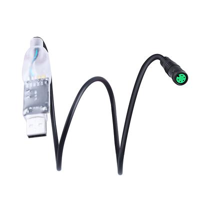
Connecting PC to Ultra Mid-Drive
- Install suite: Install software suite on your Laptop.
- Start suite: Once installed, plug programming cable in to one of the USB ports and start the program.
- Connect to Bafang Ultra: Disconnect display from wiring harness, about 500mm from display you will find socket (you can make custom wring harness in China with Y-connector if you plan to use this plug often). Plug USB programming cable in to the female socket leading to motor.
- Battery: Make sure battery is charged.
- COM Port: You are ready to connect Configuration Tool software to Motor. You need to enter COM Port in to corresponding window for tool to connect to USB dongle. If you not sure what PC port you have used to plug dongle, try entering COM1 and pressing “Connect”. If fails, try COM2 and so on.
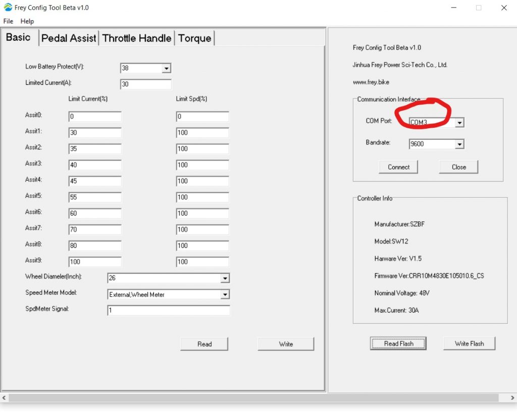
Once connected, you will get reading of Bandrate and Controller Info area populated upon you pressing “Read Flash”. At this point, it would be wise to press “Read Flash” and screenshot all four pages in order to have native settings saved as image. This will allow you to return to OEM if you desire in the future. You can also go to “FILE” and “SAVE” current flash.
READ / WRITE and SAVE
READ FLASH will read values from all four tabs at the same time.
WRITE FLASH will write values on all four tabs at the same time.
Always READ FLASH, then FILE->SAVE to make a back up copy before making any changes. This is your backup restore option.
There are four pages of variables, separated by controller module or logic. You can click READ on each page and it will only load the current settings for this page only. When you finished editing the variables and ready to apply them you need to click the WRITE for each page you edited or press WRITE FLASH to apply changes to all pages.
Basic Tab
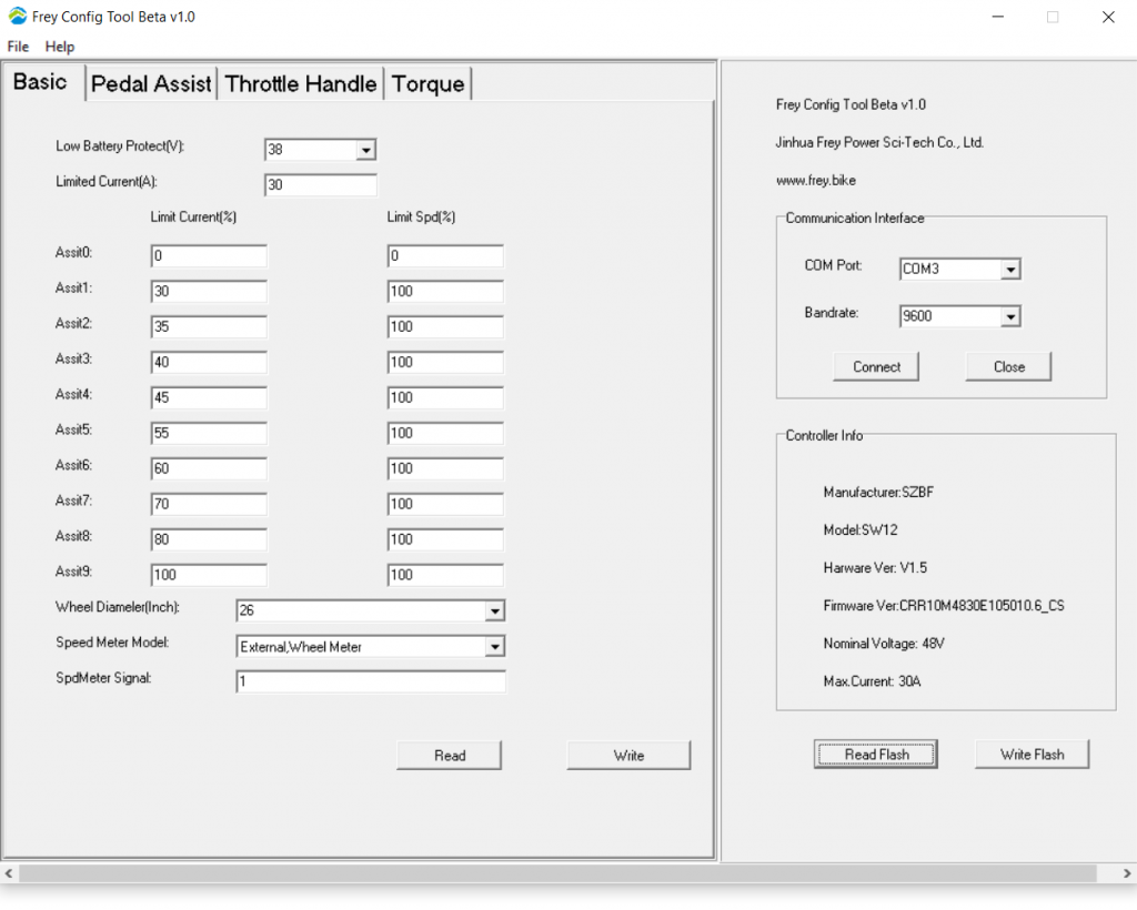
Low Battery Protect(Volts): This number will change based on the pack size and configuration. In OEM builds, battery will have internal BMS that will shut off when it gets too low. This setting is mostly useful when you are running a custom battery with voltage other than OEM.
This is the voltage at which the controller will stop the motor to keep your battery safe from over-discharge. For 13S battery packs 41V is the default.
Limited Current(Amps): This sets the maximum current level that the drive unit will pull from the battery. It can draw more current for brief periods. Maximum current is hard written in to the drive memory, you can only change to lower number than 30A.
Asst0 Limit Current(%): This is the setting for the PAS at level 0.
Range of 0-100% of maximum permitted current draw set at Limited Current(Amps) tab. The throttle might not work in PAS 0 unless this is set to 1. You must set limit speed to 1 as well as well as setting the Designated Assist to 9 on the throttle page. Keeping this to 0 enables assist OFF mode, it will ride like non assisted bike.
Asst0 Limit Spd(%): Range of 0-100% of maximum permitted motor RPM, where 50% would limit motor speed to 50% . At power level 0 the controller will lower current to maintain motor rpm below pre-set % of maximum motor RPM. Speed limiting is done based on motor RPMs not road speed. The throttle might not work in PAS 0 unless this is set to at least 1.
Asst1 Limit Current(%): Power cut based on road speed at power level 1
Asst1 Limit Spd(%): Power cut based on motor RPM speed at power level 1
Asst2 Limit Current(%): Power cut based on road speed at power level 2
Asst2 Limit Spd(%): Power cut based on motor RPM speed at power level 2
Asst3 Limit Current(%): Power cut based on road speed at power level 3
Asst3 Limit Spd(%): Power cut based on motor RPM speed at power level 3
Asst4 Limit Current(%): Power cut based on road speed at power level 4
Asst4 Limit Spd(%): Power cut based on motor RPM speed at power level 4
Asst5 Limit Current(%): Power cut based on road speed at power level 5
Asst5 Limit Spd(%): Power cut based on motor RPM speed at power level 5
Asst6 Limit Current(%): Power cut based on road speed at power level 6
Asst6 Limit Spd(%): Power cut based on motor RPM speed at power level 6
Asst7 Limit Current(%): Power cut based on road speed at power level 7
Asst7 Limit Spd(%): Power cut based on motor RPM speed at power level 7
Asst8 Limit Current(%): Power cut based on road speed at power level 8
Asst8 Limit Spd(%): Power cut based on motor RPM speed at power level 8
Asst9 Limit Current(%): – Power cut based on road speed at power level 9
Asst9 Limit Spd(%): Power cut based on motor RPM speed at power level 9
Attention:
If your display is set to only use 5 power levels then the controller uses settings for Asist Levels 1\3\5\7\9
Wheel Diameter(Inch): Set this to whatever your wheel diameter is. This will affect speedo read-out.
Speed Meter Model: ExternalWheelMeter is the only function I seen used.
SpdMeter Signal: This affect speedo. Number of pulses/signals that equate to one rotation of wheel.
Pedal Assist
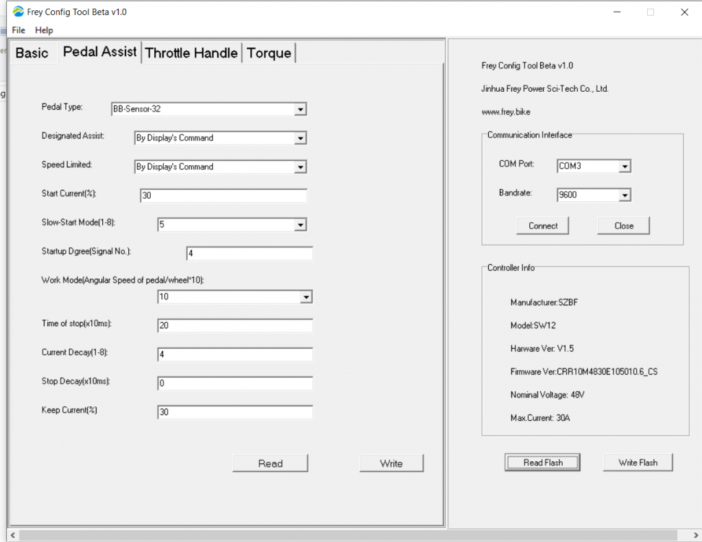
Pedal Type: Function is unknown
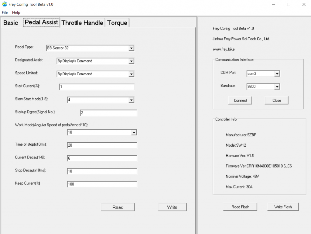
Designated Assist: You have two type of operation selected with this parameter. First is “By Display’s Command”. This means that the assist level (the one from the Basic settings tab) will be selected from your LCD. The second option is to choose a specific assist level which will be fixed and you will not be able to change that from the LCD. For this you can select any assist level from 0 to 9.
Speed Limited: Reduces power to motor when the road speed goes over the number set here. If set to By Display’s Command, uses the Display’s set speed limit.
Start Current (%): The lower the Start Current % is set less power been sent to motor upon initial start-up when you start pedalling from stand-still. Think about inductive saturation of motor and inrush currents. Lower number will result in smoother motor engagement. Higher number will result in high power kick by the motor.
Slow-Start Mode(1-8): Controls Start Current ramp and overshoot. This setting controls how quickly the start current is reached. You can make your bicycle accelerate smoothly and make it respond quickly. A value
around 4 usually works well for normal cycling. If you are mountain-biker then setting to a low value will make the acceleration faster which might be useful but you should be careful not to fry your controller and motor.
Startup Dgree(Signal No.): The number of signals from HALL Sensor before the start up commences. Lower number will result in less pedal movement to start the motor / PAS. Can be problematic below 2.
Work Mode (angular Speed of Pedal/wheel*10): Control the power according to pedal rotation speed. The value set by manufacturer seems to work just fine so you don’t need to change it.
Time of Stop(x10ms): Time in miliseconds till motor assistance switched off after you stop pedalling. While setting this number lower feel more natural when you come to stop, this will also start to affect PAS system as it will start to cut in-out between pedalling cadences. This becomes noticeable below 10.
Current Decay(1-8): This sets how fast the current decay when pedalling stopped or you are reaching the maximum speed at the selected assist level. Lower value means the current will start to drop at lower slower/more gradual.
Stop Decay(x10ms): Time in milliseconds “Current Decay” is active for, after you stop pedalling. Higher number will result in gradual power cut. While zero, will result in immediate power cut.
Keep Current(%): Percentage of the maximum current that will be flowing through the motor when you reach the maximum speed and keep pedaling. If your maximum current is 30A and you use PAS5 set to 50% current then you will have maximum current of 15A for this assist level. Then if Keep
Current is set to 50% when the maximum speed is reached and you continue pedalling the current will be kept at 7.5A. This ensures smooth transition to power assist when you reduce the pedalling speed and the moving speed drops below the maximum allowed.
Throttle Handle
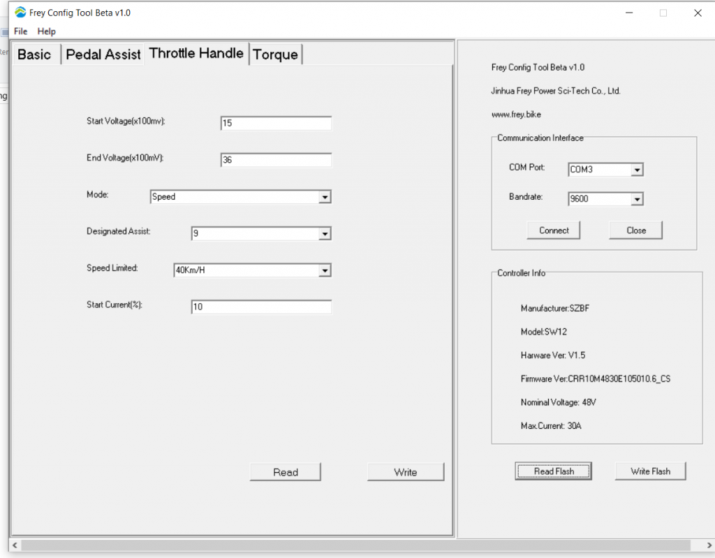
Start Voltage(x100mv): This is minimum voltage that enables throttle operation. Generated by Throttle Thumb controller on you handle bar. Different throttle controllers output different voltages at rest/off. Set to low and the display will throw an error as the motor will want to run continuously. If you change the throttle you will need to find the new lowest setting.
End Voltage(x100mV): This is maximum throttle output voltage that controller will accept. It should be matched to throttle MAX position output voltage. Best way to do so is to take some reading with multimeter at throttle socket while pressing throttle to MAX. Throttle operating span will be calculated as End Voltage – Start Voltage = Voltage Span that represent 0-100% throttle control.
Mode: Switching this to Current Mode (instead of Speed mode) has an improvement in the throttle smoothness. In Speed Mode throttle position correspond to specific calculated bike speed. In Current Mode throttle position correspond to specific calculated current output.
Designated Assist: If you disable the PAS system then this will give you the same number of levels of throttle power as PAS settings. If you don’t disable the PAS system then you should probably set this to 9. This setting will override the Limit Speed setting on the Basic Tab and also overrides the speed limited on the Basic Tab.
Speed Limited: Cuts power when the road speed reach the number set here. If set to By Display’s Command then it uses the Display’s set speed limit.
Start Current(%) : Percentage current of available when throttle initially applied. Lower number is smoother engagement but slower of the mark.
Torque mapping
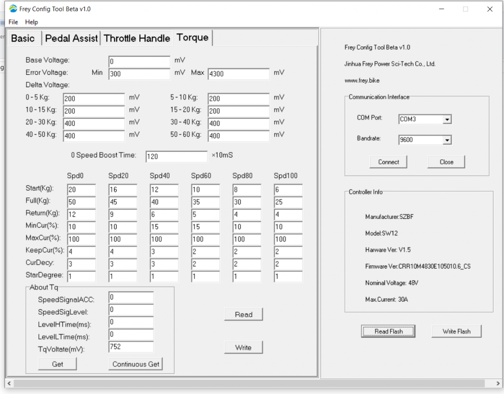
The Bafang Ultra is 1500 Watt system. Changes to Torque mapping have dramatic effect on motor and bike behaviour. High degree of safety must be considered when testing those settings.
Base Voltage: Voltage, which software will use as starting voltage for calculation of pedal load.
Error Voltage Min \ Max: This is working SPAN of voltage generated by torques sensor. If sensor output voltage fall outside specified voltage span, error mode is triggered.
Delta Voltage: This is voltage SPAN in millivolts that program use to calculate load applied to pedals. For example, for the first 200mV load cell output, program will calculate as 0-5Kg load. If you are to change 200mV to 400mV, software will now calculate load of 0-5Kg over first 400mV. This is good instrument to manipulate sensitivity of the pedal assist. From linear to progressive or any other.
0 Speed Boost time: Amount of time power is applied to motor when initial pedalling take place with bike starting speed as stationary. This is useful to program as hill-assist start.
SPD0-SPD100: Representation of motor speed in percentage steps.
Start(Kg) : Minimum Kg applied to pedal before controller will start motor and you will get the MinCur% amount of power (based on the Limit Current% variable from the first page based on your PAS level) to the drive unit which will steadily be increased based on the amount of pressure until it hits Full(Kg).
Full(Kg) : Maximum Kg applied to pedal before controller will get the MaxCur%.
Return(Kg) : Minimum required pressure on pedal in Kg to keep PAS active during pedalling. In case of setting this to ‘0’ system default to hard present system minimums that are higher than ‘0’ value.
MinCur(%) : This number must be less than MaxCur(%). This is a percentage of the Limit Current% from page one based on the current PAS setting on display that will be applied when the Start(Kg) pressure is applied to the bike based on the speed that the crank is currently turning (Spd0-100).
MaxCur(%) : This is a percentage of Limit Current% from page one based on the current power level setting on the PAS display that will be applied when Full(Kg) pressure is applied to the bike based on the speed that the crank is currently turning (Spd0-100). Useful to program various power output levels across motor RMP range. For example, 100% torque at slow speeds and gradual drop off of power as motor RPM increases.
KeepCur(%) : This number must be equal or less than MinCur. Amount of current applied between pedal strokes.
CurDecy : Rate at which KeepCur(%) fade away. 1 is been fastest.
StarDegree : Untested
About Tq : This is testing and calibration feedback area.
TqVoltate(Mv): This is Torque Cell output in raw format (mV). Useful for calibration and testing load cell. If you press Continuous Get and apply pressure on pedal mV reading will change in accordance to load applied. Bafang use inductor manufacturer in china to get custom torque/load cells made.
Bafang Ultra “Smooth” tune
Updated on 12/01/2021
Below you can find copy of our version of “SMOOTH” tune. The aim of the changes in settings was to bring Bafang Ultra Programming as close as possible to smooth operation of say Bosch or Yamaha motors.
It must be understood that Bafang allow changes to most but not all settings. Number of critical parameters are hard coded and cannot be accessed via programming suite. For example, you cannot get motor to start assisting until pedal pressure is over few Kg and bike sensors record wheel spinning. While this is safety future to avoid motor run-away, this does not permit us to enable smooth start-up procedure as there is power cut until safety systems parameters are meet.
This tune is well suited to mild track/trails and street. It is not aggressive enough for competitive racing. It will deliver predictable and progressive power & good battery life.
When testing this tune, make sure to test it in SPORT mode, not ECO. Eco mode have hard programmed function of disabling pedal assist at low pedal pressure, this cannot be overwritten. Tune below is focused on refining SPORT mode.
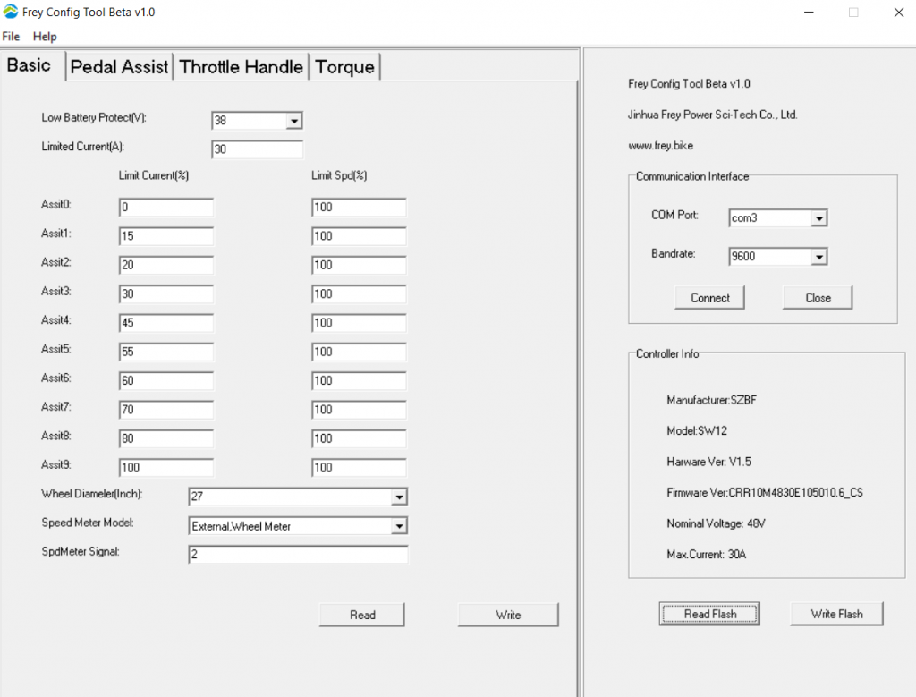
Bike had second magnet added to rear wheel for speed sensor! This greatly improves speedo responsiveness as well as assist to remove some lag in PAS start up procedure.
Make sure to change SpdMeter Signal from 1 to 2 to get correct speedo reading.
Below torque chart have do be understood with some background information. First is “Delta Voltage” This is relationship between load cell that read rider input in form of pedal pressure applied to voltage system translate this into. Delta Voltage also tied up to the range/output voltage span of load cell. If you activate “Continuous Get’ function, position bike pedals parallel to the ground and put all your weight on one pedal, you will get a reading in mV something like 3,260mV. This number less static base voltage output of the load cell of 750mV equals to about 2,500mV. This means, load cell output when you ride will be within this range.
In below Delta Voltage table you will find progressive relationship between Kg vs mV. This is done to allow rider to experience more natural and smooth assistance performance. 0-5Kg have a larger voltage span to allow for ‘ghost pedalling’ low assistance under very light pedal input. This is useful primarily when riding on pavement around town at speeds under 20Km/h. As rider increase pedal pressure, system will offer progressively more assistance. That will offer most natural feel, as human muscle is not very good in controlling force close to maximum loads.
Another aspect is Full(Kg) vs Spd.
To understand it’s progressive nature in settings let’s take a look at relationship between peak torque, peak power and pedalling cadence data from institute of sport.
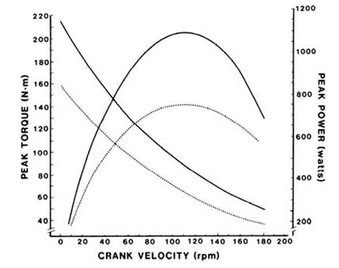
Dotted and solid lines represent data from two different riders. Notice that although peak torque (turning force) is made at low rpms, maximum power is made in the region of 110-120rpm
As you can see, rider torque/load applied to pedals is inversely progressive. We put out four times more load on pedals at stand still (body weight) compared to max RPM. Therefore to utilise entire range of motor assist power, we need to reduce the working range (Kg) as RPM increase. Failure to do so, will just mean that rider cannot access majority of Pedal Assistance at maximum RPM as full (Kg) cannot be applied to pedals.
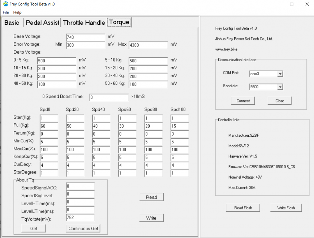
We tested Bafang Ultra settings on Frey EX bike extensively over few months of trial and street. Settings keep on evolving, please check here, we will update files as they change.
Conclusion of the Bafang Ultra programming
The 2020 Bafang Ultra controller is stable, efficient and easy to program. It offer wide range of input voltages from the batteries 48V – 60V and deliver outstanding raw power. There are some inherent non changeable issues, motor engagement on start and low cadence low power motor assist been inconsistent. Both of those issues are related to hard coded firmware and cannot be addressed in user setting menu. We are excited about Bafang’s upcoming update of the controller in 2021-2022 with major redesign of PCBA and firmware with focus of refinement to match Big Brand Euros.
If you’re interested in how Bafang Ultra is integrated in to Frey EX bike and it’s performance, please check our Frey EX review. More on the Bafang Ultra reliability review can be read here.
Found review, summary and comparison tables on this forum: https://electricbikereview.com/forums/threads/bafang-ultra-smooth-tune-by-mike-at-frey.42394/page-14